- PRIVATE ENGINEER -
Since I'm not tuning for a radio station per say and more looking for a response the antenna might only need to be a mass. I put together a basic AM loop antenna that I've been testing with some other circuits and it seems to provide the feed back fairly well, I've also found with some circuits a 15ft long wire works well which leads me to believe it's more related to mass. I'm up in the air about the antenna ( size, length, shape ) - I simply don't know at this point and still learning, it's still an unknown variable that might change with every other variable of the build. Wish I could be more specific. The one I'm playing with now is the " R & D Loop" from http://makearadio.com/loops/index.php
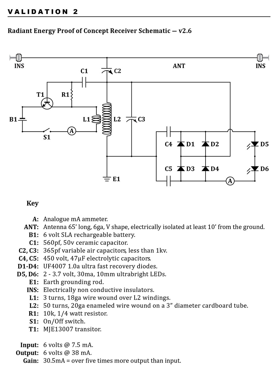
I wound the mystery coil with 20 ga wire for both coils. I didn't use the 25 turn coil with the original and wound a separate coil around it for this one. The form was a 3" diameter cardboard shipping tube. I would imagine the 24 ga wire would increase the inductance somewhat - not sure how much difference it would make.
Since the unit makes very little power the 4148's work well, I used the UF4007's on this one. I never tried the Schottkys as I didn't have any to hand.
I used two 47uf 450 volt caps on this one - again this is another variable that might require some experimentation - maybe it would work well with larger ones.
The grounds are at an advantage the deeper you can get them. A well pipe makes a very good ground as it connects into the water table. We also have a very high iron content in the ground here which I'm sure helps in the electrical activity. A shallow grounding will need to be kept wet - if rods are used I would sink several of them in a circle and connect them all together then put a sprinkler over them for a few hours to really saturate the area. A lake or stream might work very well also...
I'm sure everyone is going to end up with something a little different than the original with varying degrees of successes and/or failures because of all the variables - hopefully getting one to work better than mine. I spent 6 hours tuning, tweaking and swapping parts to get it working as shown. Everything will affect it's operation.
It's not just the components that can vary the outcome it's also the environment it's tuned to. If your sitting close to the circuit while tuning then you become a capacitive part of its environment, you may find that when you walk away it performs better or worse. A coffee cup - potted plant, electrical wiring in the home - everything absorbs or reflects energy and will have an impact on the outcome of these low power circuits. If someone built a circuit in their kitchen and tuned it perfectly showing positive results then took the same circuit without changing anything to the friends house to show them it might not work at all.
There is no clear solution other than maybe creating a "standard" environment for the circuit - a box of sorts, faraday cage? - to reduce the unaccounted for variables.